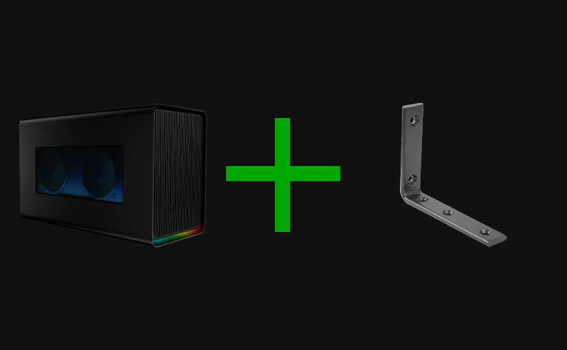
e-GPU Plus Bracket
Razer Core X Chroma is an excellent device, but its functionalities didn’t fully cover my use case. As such, I decided to add a bracket and a PCI-e extender to the mix.
Introduction
Long gone are the days where I had a desktop and a laptop computer. One for gamming and work, and the other for work alone while away from home. When time came to upgrade my setup, I decided I didn’t want to have to keep syncing files (e.g., virtual machines) in between both devices.
Yet, I also didn’t want to lose the possibility to play games. After establishing requirements and budget, I decided to invest in a Dell XPS 15 (7590) laptop and a Razer Core X Chroma (e-GPU). While the Core X Chroma is a great device, it isn’t without its flaws. One such flaws is the lack of properly working USB ports - which has been extensively documented in many forums and reviews - and the other (not as highlighted / known) the usage of an Asix based (Ethernet to USB) network adapter.
To be fair, there is nothing wrong with the Ethernet adapter, the problem is that I do make extensive use of virtual machines while researching / developing. Virtual machines, that need to be in different segments of my network and the lack of multiple VLAN support by the Core X Chroma Ethernet adapter is a big problem for me.
This is a problem specifically on Windows, which doesn’t natively support multiple VLANs, and leaves it up to the drivers to implement this support which the Asix adapter driver does not. As such, with an Ethernet adapter that didn’t cover my use case I needed to come up with a solution.
Razer Core X Chroma
The Razer Core X Chroma has a main board with two PCI-e slots. One is used for the GPU, and the other for the daughter board that provides the USB and Ethernet ports. Having two PCI-e slots is pretty good, the only problem being that the PCI-e slot for the daughter board was placed in a way that doesn’t allow for slotting of standard following PCI-e cards.
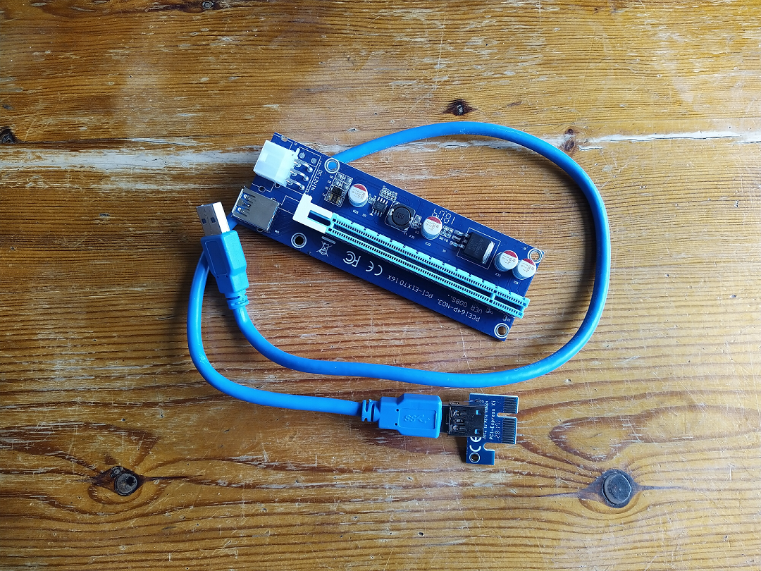
This means, that one cannot use that PCI-e slot to expand / change the e-GPU enclosure functionality by simply “slapping” an extra PCI-e card on. That got me thinking, what about those PCI-e extenders which are mostly used in crypto currencies mining? If that works one can simply place the PCI-e extender board somewhere and then connect the PCI-e device. And that is what I did.
Experimenting
Once the hardware arrived, both the PCI-e extender and PCI-e network card, the next obvious step was to experiment if this was actually going to work. I proceeded to open the e-GPU enclosure, remove both the GPU and the daughter board connect the extender, reconnect the GPU, and connect the new network card to the extender’s board.
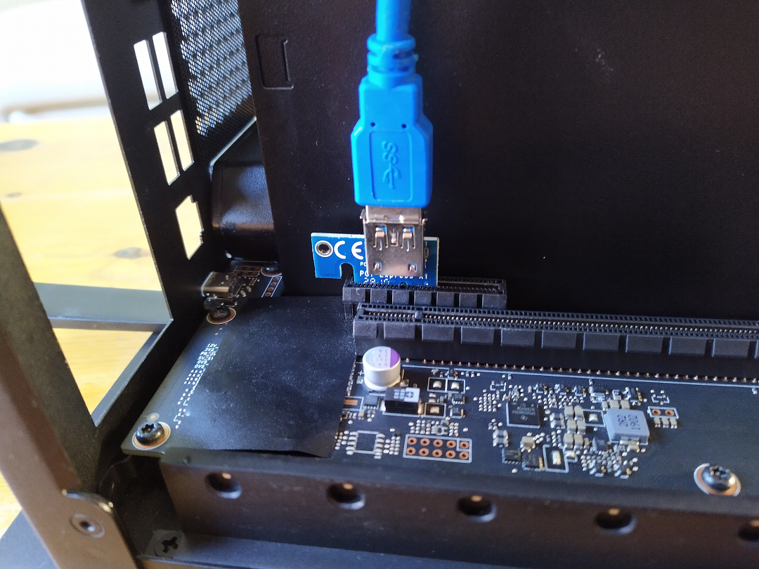
After some reboots that did very little to make things (properly) work, I found that a BIOS reset to factory defaults was all that was needed. And henceforth, both the GPU and newly installed network card were detected! I was pretty happy with the results, and the only thing left to think about was how to do the final installation.
The Bracket
After tinkering for a while on what would be the best way to “permanently” install the card I decided to make a bracket. The plan was to make use of the exhaust fan mounting holes to install the bracket. I have very little experience working with metal, so I chose aluminium as a base material for the bracket as it is generally cheap and easy to work with. The bill of materials for the bracket was:
- 1x Aluminium right-angle profile (10mm x 10mm x 1,25mm, length of at least 330mm)
- 1x Aluminium flat profile (10mm x 2mm, length of at least 400mm)
- 1x Threaded rod (M4, length of around 200mm)
- 4x Motherboard standoffs
- 4x Hex screws (M4, length of 10mm)
- 4x Motherboard mounting screws
- 8x Washers (M4)
- 12x Nuts (M4)
I cut and drilled two pieces of flat profile and two pieces of right-angle profile with the dimensions as seen in the pictures below.
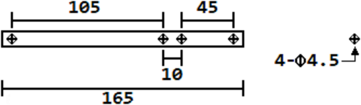
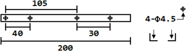
After cutting the metal profiles, I removed the e-GPU enclosure exhaust fan screws. Cut the threaded rod so it would have enough length to go through the fan, one flat profile, two washers, and screw the nuts into. Once that was done, I started getting the bracket together.
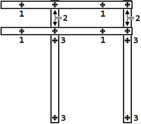
To do that, one has to get the profiles together using the M4 hex screws and M4 nuts (position 2), screw in the motherboard standoffs (position 1), install the PCI-e extender card, and get everything installed in the e-GPU using the threaded rod pieces (position 3).
Final Installation
So how does it look like? See for yourself in the photos below :D
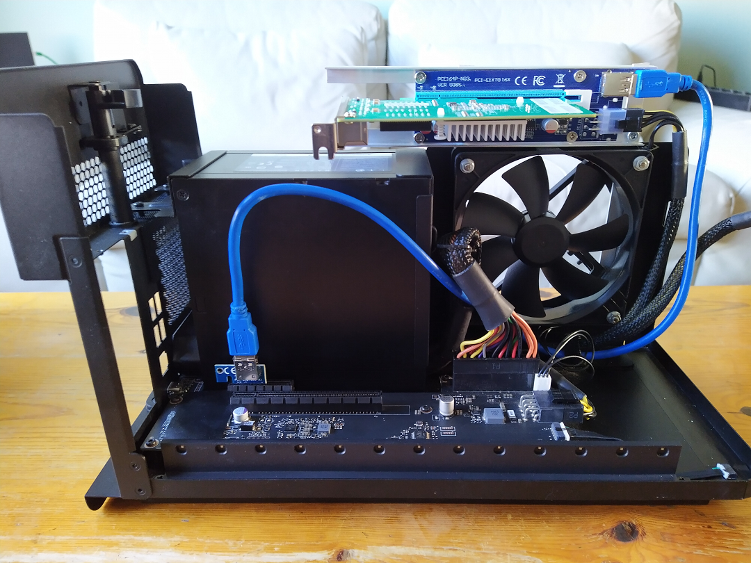
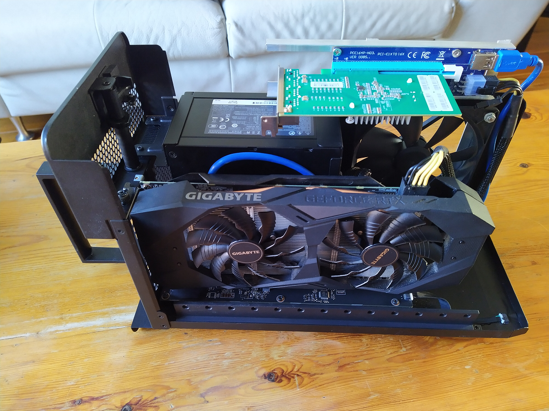
The only thing missing was to add extra support for the PCI-e card so that it won’t sag (hence the bigger overhang in the left side). Something that isn’t covered here, left as an exercise to anyone doing this hack ;)
Cheers!